
Research Article

Journal of The Korean Society of Living Environmental System. 30 June 2026. 280-287
https://doi.org/10.21086/ksles.2026.4.33.3.280

ABSTRACT


MAIN

  • 1. 서 론

  •   1.1. 연구 배경

  •   1.2. 국내·외 로보틱스 현황 및 연구 목적

  • 2. 연구 방법

  •   2.1. 연구 프로세스

  •   2.2. 자료 수집 및 분석범위

  •   2.3. 분석기법 및 절차

  • 3. 건설 로보틱스 기술의 TRL 단계 분석

  •   3.1. 일반 TRL과 건설 로보틱스 TRL 해석의 차이

  •   3.2. TRL 단계와 실증환경 구성요소의 매칭 분석

  • 4. TRL 5~7단계 향상을 위한 실증형 테스트베드 구축요건

  •   4.1. 시설기준 도출과정 및 적용범위

  •   4.2. 부지기준 도출과정 및 적용범위

  •   4.3. 제도적·운영적 구축 요건

  • 5. 결 론

1. 서 론

1.1. 연구 배경

건설산업은 인력 중심의 시공 방식에 오랫동안 의존해 왔으나, 생산인구 감소, 숙련공 부족, 중대재해 예방 요구, 생산성 정체 등의 문제로 인해 자동화 및 로보틱스 기술 도입의 필요성이 확대되고 있다(Ahn et al., 2023; Cho, Chun, & Choi, 2012). 건설 로보틱스는 센서, 제어, 인공지능, 이동 플랫폼, 데이터 통신 기술을 결합하여 반복적이거나 위험도가 높은 작업을 자동화하고, 현장 안전성과 생산성을 동시에 향상시키기 위한 핵심 기술군으로 평가된다(Choi, 2022; DARPA, 2015; Hong, Lee, & Lee, 2019).

국토교통부는 「스마트 건설 활성화 방안 S-Construction 2030」에서 2030년까지 건설 전 과정의 디지털화·자동화를 추진 목표로 제시하고 있으며, BIM, 드론, 로봇, IoT, AI 등 ICT 기반 기술의 현장 적용을 주요 정책 방향으로 설정하고 있다. 이러한 정책 흐름은 건설 로보틱스가 단순한 연구개발 대상을 넘어 현장 적용성과 상용화를 검증해야 하는 단계로 이동하고 있음을 보여준다(ISO, 2010; Jeon et al., 2020; Kwon, 2021).

다만 국내 건설 로보틱스 기술은 센서·제어·인지 등 요소기술 개발과 실험실 검증 수준에서는 일정한 성과를 보이고 있으나, 실제 현장 조건에서의 시제품 검증과 공정 통합 실증, 초기 상용화로 연결되는 TRL 5~7 단계에서는 진전이 제한적이다. 이는 실증공간, 계측 인프라, 안전관리 체계, 제도적 기준을 함께 갖춘 통합 테스트베드가 충분히 마련되지 않았기 때문이다.

1.2. 국내·외 로보틱스 현황 및 연구 목적

국외에서는 일본의 i-Construction 정책, 미국과 유럽의 자율주행 건설장비·로봇 시공기술 개발, 모듈러 및 프리패브 공정 자동화 연구를 중심으로 건설 자동화와 로보틱스 기술의 실증이 확대되고 있다. 특히 로봇 기술은 고정된 제조라인보다 불확실성이 큰 건설현장에서 운용되어야 하므로, 이동성, 조작성, 센서성능, 통신, 에너지, 안전성을 반복 가능한 시험방법으로 검증하는 체계가 중요하다(MOLIT, 2023; LOLIT, 2025).

NIST의 Standard Test Methods for Response Robots는 로봇의 이동성, 조작성, 센서, 에너지, 통신, 작업자 숙련도, 물류, 안전 성능을 정량적으로 비교하기 위한 표준시험법과 성능지표 개발을 제시하고 있다(KIRIA, 2024). 이는 건설 로보틱스 테스트베드가 단순한 공간 제공에 그치지 않고, 반복 가능한 시험코스와 객관적 성능평가 체계를 함께 갖추어야 함을 시사한다.

국내에서는 스마트건설 기술 로드맵과 스마트건설 지원정책을 통해 BIM, 드론, IoT, AI, 자동화 장비 및 로보틱스 기술의 도입이 추진되고 있다(Lee, 2023; Lee, Lee, Park, & Kim, 2025; Seo, 2020; Yun & Yun, 2025; Lee & Choi, 2025). 그러나 기존 시험·평가 환경은 개별 기술 검증 또는 제한된 실내 시험 중심으로 운영되는 경우가 많아, 대형 장비, 실외 지형, 복합 공정, 작업자-장비-로봇 혼재 조건을 포함하는 통합 실증에는 한계가 있다.

본 연구의 목적은 건설 로보틱스 기술의 TRL 향상을 지원하기 위해 TRL 5~7 단계에서 요구되는 실증환경의 구성요소를 분석하고, 시설·부지·운영·제도 측면에서 실증형 테스트베드 구축 요건을 제안하는 것이다.

2. 연구 방법

2.1. 연구 프로세스

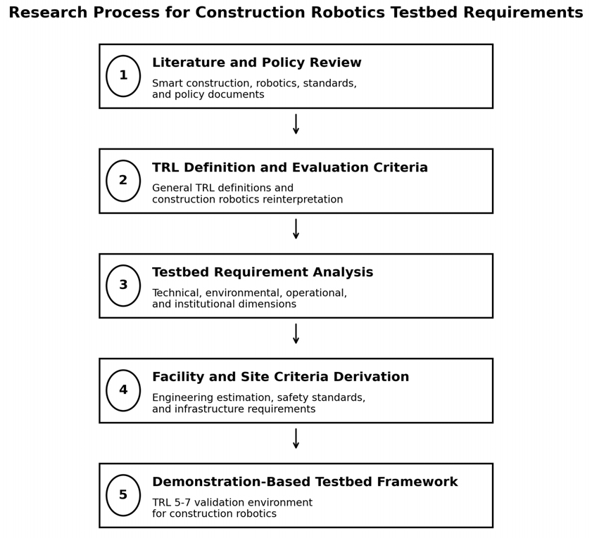
본 연구는 문헌 및 정책자료 검토, TRL 정의 및 평가기준 정리, 실증환경 요구요소 분석, 시설·부지 기준 도출, 실증형 테스트베드 구성 방향 제안의 순서로 수행하였다. 연구 과정은 Figure 1과 같이 구성하였다.
https://cdn.apub.kr/journalsite/sites/ksles/2026-033-03/N0630330302/images/ksles_33_03_02_F1.jpg
Figure 1

Research Process.

2.2. 자료 수집 및 분석범위

본 연구는 스마트건설 및 건설 로보틱스와 관련된 국내·외 문헌과 정책자료를 대상으로 자료를 수집했다. 주요 자료은 국토교통부의 스마트건설 기술로드맵, 일본 국토교통성의 I-Construction 문서, IAARC 국제학술대회 자료, 스마트건설지원센터의 실증 및 시험평가 자료, 한국건설기술연구원의 스마트건설 기술개발사업 보고서 등을 포함한다. 아울러 건설 로보틱스 기술과 기술성숙도(TRL)에 관한 국내·외 학술논문 및 기술보고서를 추가적으로 검토했다.

자료 수집은 스마트건설 및 건설 로보틱스와 직접 관련된 정책자료, 표준문서, 기술보고서, 학술논문을 대상으로 수행하였다. 주요 분석 자료는 국토교통부의 스마트건설 정책자료, NASA의 TRL 정의 및 기술성숙도 평가 지침, NIST의 로봇 표준시험법, ISO 10218·ISO 12100·ISO 3691-4 등 로봇 및 기계류 안전표준, NFPA 855의 배터리·에너지저장장치 안전기준, 국내 연구실·산업안전·지능형로봇 관련 법령을 포함한다.

분석 범위는 다음 네 가지로 설정하였다. 첫째, TRL 단계별 정의와 검증환경의 수준을 파악하였다. 둘째, 건설 로보틱스의 현장 적용 특성인 비정형 지형, 장애물, 작업자와 장비의 혼재, 통신·관제·데이터 수집 요구를 분석하였다. 셋째, 실증형 테스트베드가 갖추어야 할 시설 및 부지 조건을 산정하였다. 넷째, 테스트베드 운영에 적용될 수 있는 안전·인증·법령 요건을 검토하였다.

2.3. 분석기법 및 절차

본 연구는 문헌 기반 요구사항 분석을 적용하였다. 먼저 각 문헌에서 TRL 단계, 실증환경, 시험장비, 공간, 안전, 운영, 제도와 관련된 키워드를 추출하고, 이를 기술적·환경적·운영적·제도적 요소로 분류하였다(Table 1). 기술적 요소는 센서, 제어, 통신, 데이터, 로봇 플랫폼을 의미하며, 환경적 요소는 실내·실외 공간, 지형, 경사, 장애물, 조도 및 기상조건을 의미한다. 운영적 요소는 관제, 데이터 처리, 작업자 협업, 장시간 운영, 유지보수 절차를 포함한다. 제도적 요소는 시험기준, 안전구역, 인증, 관련 법령 및 표준을 포함한다.

Table 1

Construction Robotics Analysis by TRL Level

TRL Level Definition Construction Robotics Analysis Required Environment
TRL 1 Basic principles observed Review of Robot Operating Principles and Basic Concepts Literature-based review, no laboratory-level verification required
TRL 2 Technology concept
formulated
Identification of applicable construction processes and conceptual design of robotic systems Simulation-based validation
TRL 3 Experimental proof of
concept
Basic experimental validation of core technologies such as sensing, actuation, and control Laboratory Test Environment
TRL 4 Technology validated in
lab
Verification of basic robot operations and repeatability at the functional level Controlled indoor test environment
TRL 5 Technology validated in
relevant environment
Validation of robotic performance in partial construction processes Testbed simulating site-like conditions
TRL 6 Technology demonstrated
in relevant environment
Integrated performance validation of robot–worker–equipment collaboration Integrated testbed including sensor and communication networks
TRL 7 System prototype
demonstrated in
operational environment
Evaluation of applicability and safety under real construction site conditions Full-scale real-world testbed with operational and safety management systems
TRL 8 System complete and
qualified
Performance verification and certification based on standards and regulations Certified testing and evaluation institutions
TRL 9 Actual system proven in
operational environment
Commercial deployment and continuous operation in real construction projects Field implementation and operational evaluation

분석 절차는 다음과 같다. 첫째, NASA TRL 정의를 기준으로 TRL 5~7의 검증환경 차이를 정리하였다. 둘째, 건설 로보틱스의 특성을 반영하여 일반 TRL 요구조건을 공정 재현, 작업자-장비-로봇 상호작용, 안전구역, 계측·관제 체계로 재해석하였다. 셋째, NIST의 반복 가능한 로봇 시험방법과 ISO·NFPA 안전표준을 활용하여 시설·부지 요구사항을 도출하였다. 넷째, 제시된 수치 기준은 선행자료의 시험개념과 로봇 운용반경, 보호거리, 장비 반입 및 회차, 데이터·전력 요구량을 조합한 공학적 역산에 의해 산정하였다.

3. 건설 로보틱스 기술의 TRL 단계 분석

국내 건설 로보틱스 기술은 TRL 1~4 수준의 기초 연구 및 실험실 검증까지는 일정 수준의 성과를 보이고 있으나, 실제 환경에서의 시제품 검증과 현장 실증, 그리고 초기 상용화로 이어지는 TRL 5~7 단계에서는 기술적 진전이 제한적으로 나타난다. 이러한 현상은 실증 기반 검증 체계가 충분히 마련되지 않은 구조적 한계에서 나타나며, 상위 단계로의 성숙도 향상을 제약하는 주요 요인으로 분석된다.

3.1. 일반 TRL과 건설 로보틱스 TRL 해석의 차이

TRL은 기술의 성숙도를 1단계에서 9단계까지 구분하는 체계로, TRL 5는 관련 환경에서의 구성품 또는 시제품 검증, TRL 6은 운용환경에서의 시스템 또는 하위시스템 시제품 실증, TRL 7은 실제 운용환경에서의 시스템 시제품 실증을 의미한다. 일반 TRL은 기술 자체의 성능검증 수준을 설명하지만, 건설 로보틱스에서는 현장 환경의 불확실성과 작업자·장비 혼재 조건이 함께 고려되어야 한다.

건설 로보틱스는 제조업 로봇과 달리 고정된 생산라인이 아니라 지형, 장애물, 기상, 조도, 공정 순서, 작업자 동선이 지속적으로 변하는 환경에서 운용된다. 따라서 건설 로보틱스의 TRL 5~7 검증은 단순한 기능시험이 아니라 공정 단위 재현, 실시간 위치·센서 데이터 수집, 작업자 협업성, 안전구역, 통신 안정성, 장시간 운용 안정성을 포함하는 통합 검증으로 확장되어야 한다.

3.2. TRL 단계와 실증환경 구성요소의 매칭 분석

TRL 5~7 단계는 건설 로보틱스의 실용화 가능성을 판단하는 핵심 구간이다. TRL 5에서는 센서·제어 기능이 부분 공정 수준에서 작동하는지 확인해야 하며, TRL 6에서는 로봇, 작업자, 장비, 통신망, 관제 시스템이 통합된 상태에서 공정 흐름을 검증해야 한다. TRL 7에서는 실제 지형과 기상, 장애물, 장시간 운용 조건을 포함한 현장 수준의 검증이 요구된다. Table 2는 TRL 5~7 단계의 요구사항을 기술적, 환경적, 운영적, 제도적 구성요소로 매칭한 것이다. 분석 결과, TRL이 높아질수록 기술적 기능검증 중심에서 환경 재현성, 운영 안정성, 제도적 검증체계로 요구사항이 확장되는 것으로 나타났다.

Table 2

Mapping of TRL Levels to Tested Components

TRL Level Technical Componets Environmental Componets Operational Compoents Institutional Components
TRL 5 Sensor and control
validation equipment
Simplified relevant
environment setup
Basic data acquisition
system
Initial testing procedures
Prototype functional
testing platform
Environment enabling
partial process replication
Basic validation of
human–robot collaboration
Basic evaluation criteria
TRL 6 Integrated process-level
testing equipment
Relevant environment
reflecting workflow
conditions
Real-time monitoring and
data processing system
Process-level testing
standards
Sensor–communication
integrated system
Environment reflecting
variable conditions
(e.g., lighting, weather)
Interoperability validation Testbed operation
guidelines
TRL 7 Platform applicable to real
construction environments
Environment reflecting
actual terrain, weather,
and obstacles
On-site monitoring and
operational management
system
Field applicability evaluation
Equipment for long-term
stability verification
Full-scale test field for
complex process replication
Demonstration of
human–robot collaboration
Certification and
standardization procedures

4. TRL 5~7단계 향상을 위한 실증형 테스트베드 구축요건

4.1. 시설기준 도출과정 및 적용범위

본 연구에서는 TRL 5~7 구간에서 요구되는 실증환경의 특성을 분석하여 실증형 테스트베드가 갖추어야 할 최소 시설 요건을 도출하였다. 기준 도출은 ① TRL 단계 정의, ② NIST 로봇 시험방법의 반복 가능한 시험코스 개념, ③ ISO 10218·ISO 12100·ISO 3691-4의 위험성 평가 및 보호조치 원칙, ④ NFPA 855의 배터리 및 에너지저장장치 위험 완화 요구사항, ⑤ 로봇 운용반경과 데이터·전력 요구량에 대한 공학적 역산을 기반으로 하였다.

실내 테스트홀 규모는 로봇 회전반경, 로봇 폭, 보호거리, 센서 및 돌발거동 여유거리를 조합하여 산정하였다. 본 연구의 계획 기준은 다음 산정식을 적용하였다.

Rs=Rt+Wr/2+Sp+M

여기서 Rs는 요구 안전반경, Rt는 로봇 회전반경, Wr은 로봇 폭, Sp는 보호거리, M은 센서 및 돌발거동 여유거리이다.

Rt = 2.5~4.0 m, Wr = 0.7~1.0 m, Sp = 1.0~1.4 m, M = 0.5~1.0 m를 적용하면 Rs는 약 4.35~6.9 m로 산정된다. 따라서 실험공간 주변에는 최소 6~7 m 수준의 안전반경이 필요하다.

Lmin=Ls+2Rs+C

여기서 Lmin은 한 변의 최소 길이, Ls는 직선 주행구간, C는 회전·정지·관측장비 설치 여유공간이다. 직선 주행 10 m, 양측 안전반경, 여유공간을 고려하면 약 18~22 m가 요구되므로 실내 및 실외 시험공간의 최소 기준을 20 × 20 m로 설정하였다.

Table 3의 기준값은 모든 로봇에 동일하게 적용되는 인증 기준이 아니라, 건설 로보틱스 시제품을 TRL 5~7 단계에서 반복 검증하기 위한 계획 수준의 최소 권장값이다. 실제 구축 시에는 대상 로봇의 크기, 속도, 작업하중, 위험도, 적용 법령 및 최신 표준에 따라 조정해야 한다.

Table 3

Tested Facility Requirements for Construction Robotics

Category Facility Requirements Rationale Recommended Values
Indoor Space
Configuration
Minimum indoor test hall
size
Robot turning radius (R = 2.5–4.0 m) + safety clearance (1.0–1.4 m) → required safety radius ≥ 6–7 m. Simultaneous straight and turning operations require approximately 18–22 m. 20 × 20 m (400 m2)
Ceiling height Required for vertical operation space and sensing (e.g., LiDAR, crane interaction) ≥ 7 m
Floor load capacity To support heavy construction robots and equipment ≥ 20 kN/m2
Indoor confined-space
& obstacle zone
NIST confined-space modules typically range from 0.9–1.2 m in width. Required to replicate indoor construction environments. Based on robot width (0.7–1.0 m). Narrow passage installation
possible; modular obstacle
system
Outdoor Space
Configuration
Outdoor test yard
(mandatory)
Requires multi-terrain, slopes, and obstacle conditions. Basic course: 10 m straight + 1 slope section + 1 obstacle set (derived from layout estimation). ≥ 20 × 20 m; ≥ 2 ground
types; slope ≤ 10%
External measurement
infrastructure
RTK positioning requires open sky visibility. NIST includes outdoor camera and LiDAR observation towers. CCTV, RTK, and LiDAR
installation structures
Logistics &
Access
Large equipment access gate Based on 5-ton truck dimensions
(width 2.2 m, height 3 m), including clearance → ≥ 4.5 m required
≥ 4.5 × 4.5 m
Equipment turning &
maintenance area
Equipment turning radius 6–8 m; forklift and crane operation considered Turning radius ≥ 12 m
Fabrication
& Assembly
Robot fabrication/assembly
space
Separation of mechanical processing and electronic installation required 150–250 m2
Control &
Data
Control/AI laboratory Iterative tuning based on experimental data required. Data per experiment: 20–80 GB (4K video + LiDAR). 80–120 m2
Server room
(high heat load)
GPU and NAS generate significant heat → temperature/humidity control required 20–40 m2 + UPS
(Uninterruptible Power Supply)
Power &
Communication
Power supply Based on demonstration center benchmarks: 300–500 kVA class power reception 300–500 kVA / 3-phase 380 V
Communication
infrastructure
Real-time logging required
(50–150 MB/s)
1–10 Gbps
(Wi-Fi 6)
Data storage infrastructure 1-hour experiment generates 50–200 GB (multi-sensor data) ≥ 100 TB NAS
Safety ISO-based safety zone ISO 10218 requires protective distance, emergency stop, and physical barriers. Mobile robots require larger safety zones due to dynamic velocity changes. Configurable safety zones with
E-stop sections
Battery/high-voltage room NFPA 855 + laboratory safety regulations. Thermal runaway risk requires compartmentalization. Fire-resistant compartment +
mechanical ventilation
Operation Integrated control room Indoor and outdoor experiments should be monitored through a unified interface 40–60 m2

4.2. 부지기준 도출과정 및 적용범위

부지 기준은 Table 3에서 제시한 시설 요건을 공간 배치 관점에서 재구성하여 도출하였다. 최소 부지 면적은 실내 테스트홀 20 × 20 m, 실외 테스트야드 20 × 20 m, 안전완충구역, 대형차량 반입·회차공간, 장비 정비 및 임시 적치공간을 포함하도록 산정하였다. 부지면적은 다음과 같은 개념식으로 검토하였다.

A_site=A_indoor+A_outdoor+A_buffer+A_turning+A_logistics

여기서 A_site는 최소 부지면적, A_indoor는 실내 시험공간, A_outdoor는 실외 시험공간, A_buffer는 안전완충구역, A_turning은 차량 및 장비 회차공간, A_logistics는 장비 반입·정비·적치공간이다. 20 × 20 m 실내·실외 시험공간에 10 m 수준의 완충구역과 12 m 회차반경을 적용하면 최소 2,000~3,000 m2 수준이 요구된다.

부지 기준은 실외 주행에 따른 소음·진동·먼지, 민감시설과의 이격, 지내력과 배수, 대형차량 접근성, 고압 전력 및 광통신 인입 가능성, 공업지역 입지 적합성을 함께 고려하였다. Table 4의 값은 테스트베드 계획 수립을 위한 최소 권장 기준이며, 실제 부지 선정 시에는 지자체 도시계획, 환경·소음 규제, 지반조사 결과, 적용 로봇의 규모를 반영하여 재검토해야 한다.

Table 4

Site Criteria for Construction Robotics Testbeds

Category Site Criteria Rationale Recommended Values
Scale &
Geometry
Minimum site area Indoor (20 × 20 m) + outdoor (20 × 20 m) + buffer zone (10 m) + turning radius (12 m) → total estimated requirement of 2,000–3,000 m2. Reference: NIST minimum site (~2,700 m2). ≥ 2,000–3,000 m2
Rectangular plot
configuration
Efficient layout for straight paths (10–20 m) and slope installation. Based on NIST module block structure (~18 m). Approx. 50 × 50 m layout
feasible
Location &
Environment
Setback from sensitive
facilities
Outdoor robot operation generates noise and ground vibration. Domestic testbeds maintain separation from residential areas. No sensitive facilities within
200 m radius
Ground bearing capacity
& drainage
Considering equipment loads of 10–20 kN/m2; weak soil leads to excessive ground improvement costs. ≥ 150 kN/m2 with proper
drainage system
Climatic suitability High wind conditions can reduce the stability of aerial robots and vision-based sensing. Average wind speed ≤ 4–5 m/s
Accessibility
& Logistics
Heavy vehicle access Entrance width of 4.5 m requires road width ≥ 6 m for safe maneuvering. Road width ≥ 6 m
(turning feasible)
Accessibility to industrial
zones
Maintenance, parts supply, fabrication, and repair support should be accessible. Within 20–30 minutes from
industrial zones
Utility
Infrastructure
Power supply availability High-capacity power (300–500 kVA) required for robotics testing facilities High-voltage power
connection available
Optical network access Real-time transmission of large-scale experimental data required Fiber-optic network available
Regulatory
Compliance
Environmental regulation
compatibility
Outdoor testing generates dust and noise; industrial zoning required Semi-industrial or general
industrial zone
Safety &
Expandability
Safety buffer zone Protective distance plus unexpected robot motion range should be secured at the site boundary. ≥ 10 m from site boundary

4.3. 제도적·운영적 구축 요건

건설 로보틱스 테스트베드는 일반 실험실과 달리 건설기계, 산업용 로봇, 전기·배터리 설비, 고소·중량 작업, 영상·위치 데이터 수집, 외부 협력업체 참여가 동시에 이루어질 수 있다. 따라서 시설 구축 단계부터 연구실 안전, 산업안전, 전기안전, 화재안전, 개인정보 보호, 지능형로봇 안전성, 건설기계 관리와 관련된 법령을 종합적으로 검토해야 한다.

연구자가 상시 출입하는 공간은 「연구실 안전환경 조성에 관한 법률」에 따라 연구실 안전관리 체계와 위험성 평가가 요구될 수 있다. 또한 실증 과정에서 작업자, 장비, 로봇이 동일 공간에서 운용되는 경우 「산업안전보건법」상 위험성평가, 안전조치, 작업장 관리가 필요하다. 자율주행 이동로봇이나 무인운반차와 유사한 기능을 갖는 장비는 ISO 3691-4의 무인 산업용 차량 안전요구사항을 참고할 수 있으며, 산업용 로봇 또는 협동로봇 형태의 장비는 ISO 10218 및 ISO 12100의 위험성 평가 체계와 연계하여 검토해야 한다.

배터리 및 고전압 구동 시스템은 화재·열폭주·가스 방출 위험을 수반할 수 있으므로 별도 방화구획, 기계환기, 온도관리, 충전관리 절차가 필요하다. NFPA 855는 에너지저장장치 설치와 관련된 화재 및 안전 위험 완화 요구사항을 제시하므로, 리튬이온 배터리 기반 로봇 실증시설의 안전계획 수립 시 참고 기준으로 활용할 수 있다. 또한 실증 과정에서 수집되는 영상, 위치, 행동 데이터는 개인정보에 해당할 수 있으므로 데이터 익명화, 접근권한 관리, 보관기간 설정 등 개인정보 보호 체계가 필요하다.

5. 결 론

본 연구는 건설 로보틱스 기술의 TRL 향상을 위해 필요한 실증형 테스트베드 구축 요건을 분석하였다. 일반 TRL 정의와 건설 로보틱스의 현장 적용 특성을 비교한 결과, TRL 5~7 단계는 단순한 시제품 성능평가가 아니라 부분 공정 검증, 공정 통합 검증, 실제환경 실증으로 단계적으로 확장되는 것으로 해석할 수 있다.

첫째, TRL 5 단계에서는 센서·제어 기능과 부분 공정 단위의 작동 검증을 위한 제한적 유사환경 테스트베드가 필요하다. 둘째, TRL 6 단계에서는 로봇, 작업자, 장비, 통신망, 관제체계가 결합된 통합 테스트베드가 요구된다. 셋째, TRL 7 단계에서는 실제 지형, 기상, 장애물, 안전관리, 장시간 운용 안정성을 포함하는 현장 수준의 실증환경이 필요하다.

본 연구는 이를 바탕으로 실내·실외 각각 20 × 20 m 수준의 시험공간, 6~7 m 수준의 안전반경, 2종 이상의 지반 및 경사 조건, RTK·LiDAR·CCTV 기반 계측 인프라, 300~500 kVA 전력 인입, 1~10 Gbps 통신망, 100 TB 이상의 저장 인프라, 배터리·고전압 전용 안전구역, 2,000~3,000 m2 이상의 부지 규모 및 10 m 이상의 안전완충구역을 계획 기준으로 제안하였다.

결론적으로 국내 건설 로보틱스 기술의 상위 TRL 진입과 실용화를 위해서는 실험실 중심 연구환경을 넘어 실제 현장 조건을 반복 가능하게 재현할 수 있는 실증형 테스트베드가 필수적이다. 본 연구에서 제시한 시설·부지·운영·제도 요건은 향후 스마트건설 로보틱스 기술개발사업 기획, 실증 인프라 조성, 성능평가 체계 구축 및 관련 정책 수립을 위한 기초자료로 활용될 수 있다.


Acknowledgements

This work was supported by the Research Sabbatical Grant for Research Professors from Gyeongsang National University in 2026, GNU-SGRP-0000.

References

1

Ahn, H., Lee, C., Kim, M., Kim, T., Lee, D., Kwon, W., et al. (2023). Applicability of smart construction technology: Prioritization and future research directions. Automation in Construction, 153, 104953. https://doi.org/10.1016/j.autcon.2023.104953

10.1016/j.autcon.2023.104953
2

Cho, K. H., Chun, H. C., & Choi, D. S. (2012). Integrated environmental cost computation method in domestic construction industry. Journal of The Korean Society of Living Environmental System, 19(5), 605-614.

3

Choi, B. J. (2022). Analysis of the productivity of site installation in off-site construction using smart construction technologies. Review of Architecture and Building Science, 66(10), 31-34.

4

Defense Advanced Research Projects Agency (DARPA). (2015). Robots elicit cheers, gasps and groans: DARPA Robotics Challenge Finals test state-of-the-art robots’ ability to perform tasks related to disaster response. Arlington, VA: Author.

5

Hong, C. Y., Lee, J. S., & Lee, S. M. (2019). Preliminary feasibility study report for smart construction technology development project. Seoul: Korea Institute of S&T Evaluation and Planning.

6

International Organization for Standardization (ISO). (2010). ISO 12100:2010: Safety of machinery—General principles for design—Risk assessment and risk reduction. Geneva: Author.

7

Jeon, H. S., Jeon, Y., Rim, Y. H., Kang, B. S., Cho, Y, H., & Park, S. J. (2020). Improve the support system for SMEs’ commercialization of biohealth industry: focusing on TRL. Osong Medical Innovation Foundation, 85-88.

8

Korea Institute for Robot Industry Advancement, & Korea Association of Robot Industry (KIRIA). (2024). 2023 Korea robot industry survey report. Daegu: Korea Institute for Robot Industry Advancement.

9

Kwon, S. W. (2021). Smart construction: From the meaning of construction automation and construction robotics. Review of Architecture and Building Science, 65(3), 56-57.

10

Lee, C. G. (2023). A study of robotics 4.0 and how the robot industry will develop - Focusing on meaning, aspects, and development issues. Chung-Ang University, 89-95.

11

Lee, J. U., Lee., J. H., Park, C. R., & Kim, S. Y. (2025). Research trends in the construction field for the revitalization of smart construction technology. Korea Institute of Civil Engineering & Building Technology, 73-79.

12

Lee, W. H., & Choi, S. H., (2025). Analysis of the developement and adoption status of smart construction technologies : focusing on the k-water busan eco delta smart city case. Graduate School of Pusan National University, 7-14

13

Ministry of Land, Infrastructure, Transport and Tourism (MOLIT). (2023). Automation and remote operation of construction machinery execution. Tokyo: Author. Retrieved from https://www.mlit.go.jp/tec/constplan/content/001617602.pdf

14

Ministry of Land, Infrastructure, Transport and Tourism (MOLIT). (2025, April 18). Summary of planned initiatives for FY2025 under i-Construction 2.0: Labor-saving and productivity improvement through automation of construction sites. Tokyo: Author. Retrieved May 12, 2026, from https://www.mlit.go.jp/report/press/content/001884821.pdf

15

Seo, J. H. (2020). A study on the priority setting for smart technologies adoption at the construction companies: A house of quality perspective. Graduate School of Chungbuk National University, 13, 78-92, 138-144.

16

Yun, H. E., & Yun, M. Y. (2025). Research on ways to revitalize the construction industry through smart construction technology - AHP-based smart construction technology analysis-. Daejin University Graduate School, 26, 75-79.

페이지 상단으로 이동하기